
BCM Auto Parts
Key Features
Used to collect relevant input signals and control the operation of electrical components.

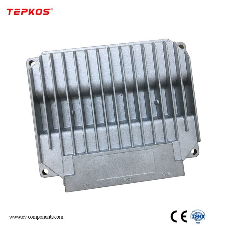
Figure 1 Module appearance
Appearance and size
The basic dimensions of the module are shown in the figure above. If specific dimensions are required, please refer to the design drawing.
Technical Parameters
Input / Output
Modules
2-way 12A power output
13 channels 9A power output
6-way 4A power output
2-way 2A power output
6-way 1A power output (with reverse protection )
1 channel 4A low-side power output
1 12V power output
1 channel 5V power output
2-way C3 vehicle speed signal output
2- way vehicle speed signal output
2 high-side digital inputs
12 low-side digital inputs
2 floating digital inputs
8-channel AI analog input
Can measure resistance change signals, such as fuel signal or temperature sensor signal. Can measure resistance change range 0-500Ω
2 pulse inputs
Can measure engine RPM or vehicle speed
1 channel frequency range 0.5-2KHz, used for vehicle speed
1 channel frequency range 2Hz -20KHz, for speed
1 low-side wake-up
1 CAN bus
1 ISO11898 (CAN2.0B) interface to communicate with the instrument main control module
You can choose whether to connect a 120Ω terminal resistor
Communication
1 ISO11898 (CAN2.0B) interface to communicate with the instrument main control module
CAN bus online and remote upgrade function
Communication protocol: canopen customized communication protocol
Connector
The module uses highly reliable Tyco automotive connectors
The module adopts 21-pin, 18-pin, 15-pin, 12-pin, 9-pin, and 6- pin plug-ins
Work Environment
Working temperature range: -30℃~+70 ℃;
Storage temperature range: -40℃ to + 85℃
Humidity and temperature: Temperature 55℃/humidity 93%, Temperature 25℃/humidity 97%
Electrical parameters
Power supply range : 12V~32V
Short circuit protection to ground or power supply
Protection against polarity inversion
Power consumption : ≤ 180W
Current in sleep mode: less than 2 mA
EMC/EMI performance
(BCI) on the wiring harness
Anti-conducted interference: BCI according to ISO11452-4, 50mA, Class B
Electrical interference on power lines and high input (ISO7637-2 )
Pulse 1: -450V; Ri = 50 ; td = 1ms, t1 = 1s, Class C. Pulse 2a: +50V; Ri = 2 ; td = 0.05ms, t1 = 1s, Class B. Pulse 2b: +20V; Ri = 0.05 ; td = 0.5s, Class C
Pulse 3a,3b: ± 200V; Ri = 50 ; td = 0.1µs, Class A
Pulse 4: Us = -12V; Ua = -5V; t7 = 100 ms; t9 = 10s, Class B
Pulse 5a: +100V; Ri = 1.5 ; td = 400ms, Class B
Electromagnetic interference
on signal lines (ISO7637-3) Pulses
a and b: ± 80V, Class B
Radiated Emissions
Complies with 2006/28/CE directive
E marking
Certification in accordance with 2006/28/CE directive
Electrostatic Discharge
Discharge directly from the connector pin through 2kΩ and 330pF: 2 kV air discharge: 8 kV
Contact discharge: 4 kV
Mechanical characteristics
shell
The module is cast aluminum housing
The housing is splash-proof
The housing has good heat dissipation, thus ensuring long-term reliability
Shock
Withstands 15 Newtons, 11ms, 3 shocks per axis per direction (18 times total), thus meeting IEC/CEI 68-2-27 test specifications
Vibration
Test 1: CEI 68-2-6, test Fc
Band [5 Hz, 27.3 Hz], with +/- 1 mm displacement
Band [27.3 Hz, 100 Hz], with 3G acceleration, 1 octave/min,
Test duration: 8 hours power off on the 3 axes (up-down, left-right and front-behind)
Installation identical to vehicle (CEI 68.2.47)
Install
The CAN bus module is fixed with 4 screws. The installation environment should be ventilated and away from heat sources, with the connector insertion port facing downward.
Pin Definition
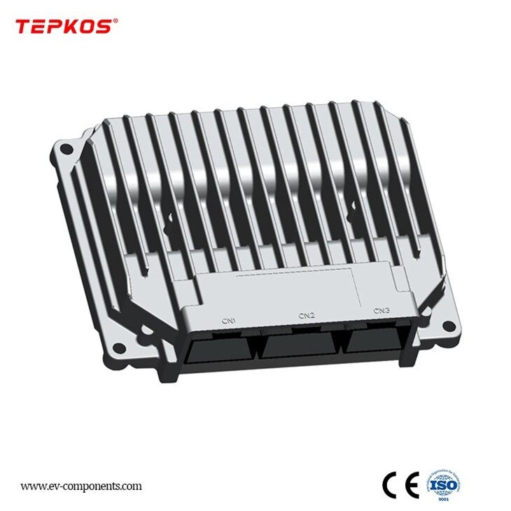
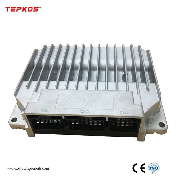
1.The connector arrangement of the IM228 module is shown in Figure
2.The connector names from left to right are CN1, CN2, CN3, CN4, CN5, and CN6.

Figure 2 Schematic diagram of IM228 module connector layout

CN1 terminal harness plug sheath AMP: 1-967625-1 ( female - brown )

CN2 terminal harness plug sheath AMP: 1-967624-1 ( female - gray )

CN3 terminal harness plug sheath AMP: 1-967621-1 ( female -- yellow )

CN4 terminal harness plug sheath AMP: 1-965640-1 ( female - blue )

CN5 terminal harness plug sheath AMP: 1-967622-1 ( female -- green )

CN6 terminal harness plug sheath AMP: 1-967623-1 ( female - purple )
Different models and configurations of IM228 modules have different functions and their pin definitions are also different. The IM228 module interface definition is shown in Table 1.
Table 1 Module pin definition
|
name |
Pin Number |
Input/Output Output Type |
Notes |
Power supply cloth |
|
OUT1 |
CN5- 04 |
High output |
Rated current 12A |
VS2 |
|
OUT2 |
CN2- 16 |
High output |
Rated current 12A |
VS1 |
|
OUT3 |
CN6- 10 |
High output |
Rated current 9A |
VS2 |
|
OUT4 |
CN1- 21 |
High output |
Rated current 9A |
VS1 |
|
OUT5 |
CN3- 01 |
High output |
Rated current 9A |
VS1 |
|
OUT6 |
CN5- 03 |
High output |
Rated current 9A |
VS2 |
|
OUT7 |
CN5- 02 |
High output |
Rated current 9A |
VS2 |
|
OUT8 |
CN2- 18 |
High output |
Rated current 9A |
VS1 |
|
OUT9 |
CN6- 04 |
High output |
Rated current 9A |
VS2 |
|
OUT10 |
CN1- 16 |
High output |
Rated current 9A |
VS1 |
|
OUT11 |
CN5- 01 |
High output |
Rated current 9A |
VS2 |
|
OUT12 |
CN6- 01 |
High output |
Rated current 9A |
VS2 |
|
OUT13 |
CN2- 17 |
High output |
Rated current 9A |
VS1 |
|
OUT14 |
CN1- 20 |
High output |
Rated current 9A |
VS1 |
|
OUT15 |
CN6- 07 |
Low Output |
Rated current L4A |
VS2 |
|
OUT16 |
CN1- 19 |
High output |
Rated current 9A |
VS1 |
|
OUT17 |
CN6- 11 |
High output |
Rated current 4A |
VB |
|
OUT18 |
CN6- 14 |
High output |
Rated current 4A |
|
|
OUT19 |
CN4- 05 |
High output |
Rated current 4A |
VS2 |
|
OUT20 |
CN4- 04 |
High output |
Rated current 4A |
|
|
OUT21 |
CN6- 13 |
High output |
Rated current 4A |
VS2 |
|
OUT22 |
CN6- 15 |
High output |
Rated current 4A |
|
OUT23 |
CN1- 10 |
High output |
Rated current 1A (with reverse protection ) |
VB |
|
OUT24 |
CN1- 14 |
High output |
Rated current 1A (with reverse protection ) |
|
|
OUT25 |
CN1- 13 |
High output |
Rated current 2A |
|
|
OUT26 |
CN1- 17 |
High output |
Rated current 2A |
|
|
OUT27 |
CN3- 04 |
High output |
Rated current 1A (with reverse protection ) |
VS1 |
|
OUT28 |
CN3- 07 |
High output |
Rated current 1A (with reverse protection ) |
VS1 |
|
OUT29 |
CN4- 02 |
High output |
Rated current 1A (with reverse protection ) |
|
|
OUT30 |
CN4- 01 |
High output |
Rated current 1A (with reverse protection ) |
|
|
31 |
CN2- 05 |
CAN wake-up Wire |
WK0_L |
|
|
32 |
CN3- 03 |
CAN Line |
CAN_GND |
|
|
33 |
CN3- 02 |
CAN Line |
CAN_120R |
|
|
34 |
CN3- 06 |
CAN Line |
CANL_I |
|
|
35 |
CN3- 05 |
CAN Line |
CANH_I |
|
|
36 |
CN3- 09 |
CAN Line |
CANL_O |
|
|
37 |
CN3- 08 |
CAN Line |
CANH_O |
|
|
38 |
CN1- 09 |
Power Ground |
GND |
|
|
39 |
CN2- 06 |
Power Ground |
GND |
|
|
40 |
CN2- 03 |
power supply |
VB |
|
|
41 |
CN2- 01 |
power supply |
VS1 |
|
|
42 |
CN2- 02 |
power supply |
VS1 |
|
|
43 |
CN2- 04 |
power supply |
VS1 |
|
|
44 |
CN6- 02 |
power supply |
VS2 |
|
|
45 |
CN6- 03 |
power supply |
VS2 |
|
|
46 |
CN6- 06 |
power supply |
VS2 |
|
|
47 |
CN5- 05 |
enter |
Positive Control |
|
|
48 |
CN5- 06 |
enter |
Positive Control |
|
|
49 |
CN5- 07 |
enter |
Negative Control |
|
|
50 |
CN5- 08 |
enter |
Positive Control |
|
|
51 |
CN5- 09 |
enter |
Positive Control |
|
|
52 |
CN1- 18 |
enter |
Negative Control |
50mA |
|
53 |
CN1- 15 |
enter |
Negative Control |
50mA |
|
54 |
CN1- 12 |
enter |
Negative Control |
50mA |
|
55 |
CN1- 11 |
enter |
Negative Control |
50mA |
|
56 |
CN2- 09 |
enter |
Negative Control |
|
|
57 |
CN2- 08 |
enter |
Negative Control |
|
|
58 |
CN2- 11 |
enter |
Negative Control |
|
|
59 |
CN2- 12 |
enter |
Negative Control |
|
|
60 |
CN2- 10 |
enter |
Negative Control |
|
|
61 |
CN2- 13 |
enter |
Address Lines |
|
62 |
CN5- 11 |
enter |
UIN0 |
|
|
63 |
CN5- 10 |
enter |
UIN1 |
|
|
64 |
CN2- 14 |
enter |
OIN0 |
|
|
65 |
CN2- 15 |
enter |
OIN1 |
|
|
66 |
CN5- 12 |
enter |
FIN0 |
|
|
67 |
CN1- 01 |
enter |
AIN0 |
|
|
68 |
CN1- 02 |
enter |
AIN1 |
|
|
69 |
CN1- 03 |
enter |
AIN2 |
|
|
70 |
CN1- 04 |
enter |
AIN3 |
|
|
71 |
CN1- 05 |
enter |
AIN4 |
|
|
72 |
CN1- 06 |
enter |
AIN5 |
|
|
73 |
CN1- 07 |
enter |
AIN6 |
|
|
74 |
CN1- 08 |
enter |
AIN7 |
|
|
75 |
CN6- 08 |
Output |
FOUT0 |
|
|
76 |
CN6- 12 |
Output |
FOUT1 |
|
|
77 |
CN6- 05 |
Output |
FOUT2 |
|
|
78 |
CN6- 09 |
Output |
FOUT3 |
|
|
79 |
CN4- 03 |
Output |
P12_O |
|
|
80 |
CN4- 06 |
Output |
P05_O |
|
|
81 |
CN2- 07 |
Output |
illustrate:
V1\V2 is ACC gear power supply controlled by the main power switch, VB is normal fire power supply not controlled by the main power switch.
The rated current is the current for long-term operation (more than 1 hour at a time) under rated load conditions. The short-term operation (less than 1 minute at a time) can exceed the rated current by about 20%.
LIN represents a low-effective input signal, HIN represents a high-effective input signal, AIN represents an analog input signal, OIN represents a floating input signal, and FOUT represents a frequency output.
CAN Bus System Application Guide
Heat dissipation
The system equipment generates heat during operation. Please do not install the CAN bus module near overheating parts such as exhaust pipes.
Avoid installing system equipment in narrow spaces to prevent accelerated aging or damage of the equipment.
Power limit per unit: The module has thermal power consumption limit, the thermal power consumption is 11W at an ambient temperature of 50℃, and the thermal power consumption is 7W at an ambient temperature of 70℃
Mechanical structure
Fixing and vibration
Use 6 flat head screws, with or without locking washers, tighten 10N/m
Installation surface flatness : 0.5mm/100mm
Surface protection grade
The dust and water resistance level of the digital LCD instrument is IP40 (after installation on the instrument panel). When the module uses a sealing gasket on the connector, the dust and water resistance level is not less than IP65 (to prevent dust intrusion and water splashing).
illustrate:
When installing and using system equipment, take all necessary precautions to prevent liquids from entering or accumulating on or inside the equipment.
System equipment is sensitive to mechanical shock. Be careful to prevent it from falling during movement, installation and use.
Electromagnetic compatibility
Wiring harness installation requirements:
Generally speaking, the connection between sensors and system equipment should be as short as possible.
Analog signals should be shielded or close to the ground
Sensitive signal (high-precision analog signal) cables should be kept away from high-current cables
The cross-sectional area of the cable that transmits the oscillation signal (such as PWM signal, minimum current 1A) should not be less than 1mm2 and should be arranged close to the ground wire.
Cables are not placed near metal structures
Installation location
The module is installed vertically (heat sink vertically).
All connection and fixing points are easily accessible (installation and maintenance ) wiringconnectFor CAN bus products, please disconnect the power supply when connecting or disconnecting the wiring harness connector, otherwise it will affect the service life and even damage the product.
Battery charging equipment sometimes generates instantaneous high voltage that exceeds the standard voltage, which may damage or even destroy the equipment's surge protection components. Precautions: Disconnect equipment while battery is charging.
ECU Impedance between sensor and actuator
To ensure correct operation and short-circuit current protection, the impedance between the ECU and the sensor/actuator must meet the following requirements (including the impedance of the cable and connector)
Battery "+" pole impedance 0.3Ω
Battery "-" pole impedance 0.3Ω
The impedance between the sensor ground and the vehicle body ground is < 1Ω Output:
LS5A output impedance < 1.2Ω
HS1.5A output impedance < 6Ω
HS2A output impedance < 3Ω
HS3.2A output impedance < 3Ω
HS7A output impedance < 2Ω
HS9A output impedance < 0.6Ω
Input characteristics
Analog signal input
For specific parameters of the analog signal input voltage range, please refer to the digital LCD instrument or module input signal Technical characteristics. The input is protected against voltage surges. However, the analog detection characteristics cannot be guaranteed during voltage surges.
Key Points
The emergency signal input should be connected to the main control module (digital LCD instrument) to ensure normal operation when the CAN network fails.
The input pin is protected against surge voltage up to 50V ( e.g. inductor demagnetization).
Output Characteristics
Output open circuit detection
Open circuit detection threshold between meter and module:
LS output impedance < 200KΩ (battery voltage 28V)
HS output impedance < 520Ω (battery voltage 28V)
Wiper brush control
Make sure that the brush output voltage does not exceed 56V when the wiper motor switches from low speed to high speed.
CAN bus network wiring requirements
Wiring requirements
CAN high and CAN low lines must use shielded cables, and the shield must be connected to the ground wire of the ECU. The current cross-sectional area should not be less than 0.5mm2.
Wiring requirements
The line layout of the network should be as close to a linear arrangement as possible to avoid cable reflection. In practice, it is necessary to use a short stub to connect to the trunk cable. In order to minimize standing waves, the spacing between nodes in the network should not be the same, and the length and size of the short stub should not be exactly the same. The specific form is shown in Figure 3

Figure 3 Network
Product Application

Production Details

Product Qualification

Deliver, Shipping and Serving


