
TFT Cluster Display (CM228)
Technical Characteristics
Human-Machine Interface
☆2 stepper motor-driven gauges
☆15 warning indicators
☆True color TFT LCD display
☆4 TFT screen control buttons
☆One multi-audio buzzer
Input
☆Up to 4 analog video camera terminal inputs
☆40 low-side/high-side digital signal inputs
☆8 universal logic signal inputs, configurable as 5 low-side/high-side inputs and 3 low-side/frequency outputs
☆6 analog signal inputs, variable resistance measurement range 0-500Ω
☆3 frequency signal inputs, can measure engine RPM or vehicle speed. Frequency range 0.5-2KHz
☆6 wake-up digital signal inputs, including 3 low-side wake-up and 3 high-side wake-up
Output
☆2 vehicle speed signal outputs
☆1 C3/B7 signal output
☆1 sensor power output (100mA@8V)
Communication
☆2 ISO11898, CAN2.0 interfaces
☆One connected to the intelligent body CAN network (e.g., BCM module)
☆One connected to the powertrain system (e.g., ABS system, engine, etc.) via SAE J1939 protocol
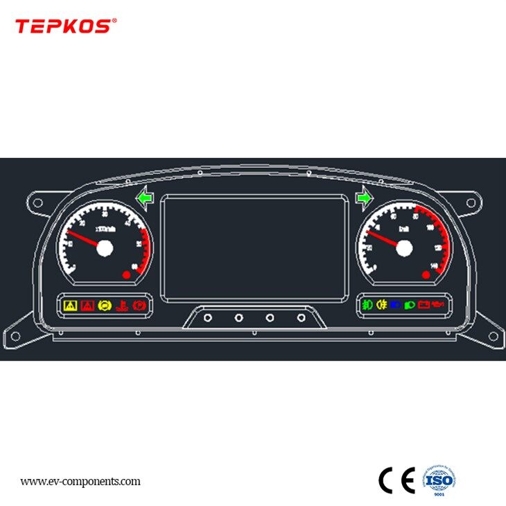
Human-Machine Interface Description
Front Panel

Instrument and Warning Indicators
| Serial Number | Name | Description |
|---|---|---|
| 1 | Engine Tachometer | Range 0-3000RPM, 1000-2000RPM is the green area, 2500-3000RPM is the red area |
| 2 | RPM Overspeed Indicator | Red light on when engine RPM exceeds 2500 |
| 3 | Left Turn Indicator | Green light flashes and buzzer sounds when turning left |
| 4 | Handbrake Indicator | Red light on when using the handbrake |
| 5 | Low Beam Indicator | Green light on when the low beam is turned on |
| 6 | Door 1 Open Alarm | Yellow when the door 1 open signal is valid |
| 7 | Door 2 Open Alarm | Yellow when the door 2 open status signal is valid |
| 8 | General Fault Warning Light | Yellow light on and fault information is displayed at the bottom of the color TFT screen when an abnormality is detected. For example, if there is a low beam fault, the general warning light will turn on and the TFT screen will display "Please check the low beam" and other fault information |
| 9 | High Beam Indicator | Blue light on when the high beam is turned on |
| 10 | Emergency Fault Warning Light | Red light on and buzzer sounds for 3 seconds when an emergency fault is detected. If this light is on, the driver must immediately stop the vehicle urgently to resolve the fault. For example: low air pressure, high coolant temperature, low oil pressure, low coolant level |
| 11 | Water Temperature Alarm Light | Red light on when the water temperature alarm signal is valid |
| 12 | Front Fog Light Indicator | Green light on when the front fog light is turned on |
| 13 | Rear Fog Light Indicator | Yellow light on when the rear fog light is turned on |
| 14 | ABS Warning Indicator | Yellow light on when there is an ABS fault |
| 15 | Right Turn Indicator | Green light flashes and buzzer sounds when turning right |
| 16 | Overspeed Indicator | Red light on and buzzer sounds for 1 second when the vehicle speed exceeds 110km/h |
| 17 | Speedometer | Measurement range 0-140Km/h |
| 18 | Menu Button | Press and hold for 3 seconds to switch from the main interface to the diagnostic interface. Use the "+" and "-" buttons to browse pages in the diagnostic interface |
| 19 | "+" Button | Four functions: 1. Increase brightness when adjusting brightness in the video surveillance interface; 2. Increase contrast when adjusting contrast in the video surveillance interface; 3. Increase backlight when the outline light is on; 4. Next page in the diagnostic interface |
| 20 | "-" Button | Opposite functions to the "+" button |
| 21 | Confirm Button | Select the current item |
TFT Display
This TFT display has three interfaces:
Main interface
Diagnostic interface
Video surveillance interface
Main Interface
When in the main interface, the following information is displayed on the screen:
Diagnostic information
Trip mileage and cumulative mileage
Indicator icons
Pressure gauge
Vehicle operating status
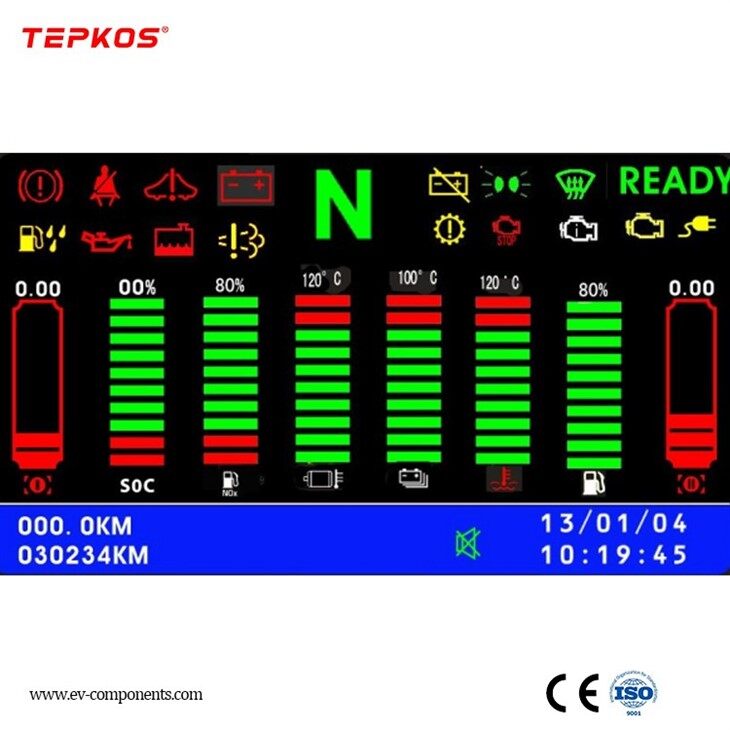
Under normal conditions, the TFT LCD screen displays the following information, as shown in Figure 2 (the liquid crystal display interface can be customized)

Description: This tft cluster display battery total voltage, total current, motor speed, maximum single battery voltage, minimum single battery voltage, maximum battery pack temperature, minimum battery pack temperature, battery SOC status, pure electric driving mode, total cumulative mileage, short cumulative mileage, time, alarm icons, alarm text, etc.
Diagnostic Information
In the bottom blue area of the screen, diagnostic information is displayed in plain text. An icon is displayed before the information for quick identification of the information type. Diagnostic information is displayed item by item.
Trip Mileage and Cumulative Mileage
The trip mileage can be cleared through the menu and confirm button.
Battery Voltage and Charge Status Indicator
In addition to the 2 traditional pointer-type instruments, the TFT screen can add instruments to display battery voltage, air pressure, fuel level, etc. Information is displayed in the form of a bar graph or text, with eye-catching red for easy identification of voltage and fuel level.
Indicator Icons
In addition to the 15 warning indicators on the Koster color screen instrument panel, indicator icons (customizable) are also displayed on the TFT screen, as shown in Figure 8. Examples of warning icons are shown in Table 3.
Table 3 Warning Icon Examples
|
1 |
Coolant Low Warning, Red |
|
|
2 |
Seat Belt Indicator, Red |
|
|
3 |
Drive Fault, Red |
|
|
4 |
Ready to Run, Green |
|
|
5 |
Defrost, Green |
|
|
6 |
Power Battery Cut-off Indicator, Yellow |
|
|
7 |
Engine Not Running Indicator, Red |
|
|
8 |
Engine Oil Contains Water, Yellow |
|
|
9 |
Gear Indicator, Green/Red |
|
|
10 |
NOx Emission Fault, Yellow |
|
|
11 |
Transmission Fault Warning, Yellow |
|
|
12 |
Severe Engine Fault Warning, Red |
|
|
13 |
OBD Warning, Green |
|
|
14 |
Engine Fault Warning, Yellow |
|
|
15 |
Battery Charging Indicator, Yellow |
|


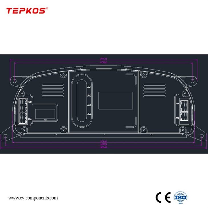
The interface of CM228 connected to the outside

Deliver, Shipping and Serving


